Process Model
In eizen agentic platform, workflows are primarily built using process models, which allow developers to visually design and organize the flow of tasks. These models can assign work to users, manage and update data, trigger system-level actions, or interact with other design components. They are commonly linked with record types, enabling users to perform actions based on the data displayed. This section explains the fundamental features and uses of process models, along with how to work with them using the Process Modeler tool.
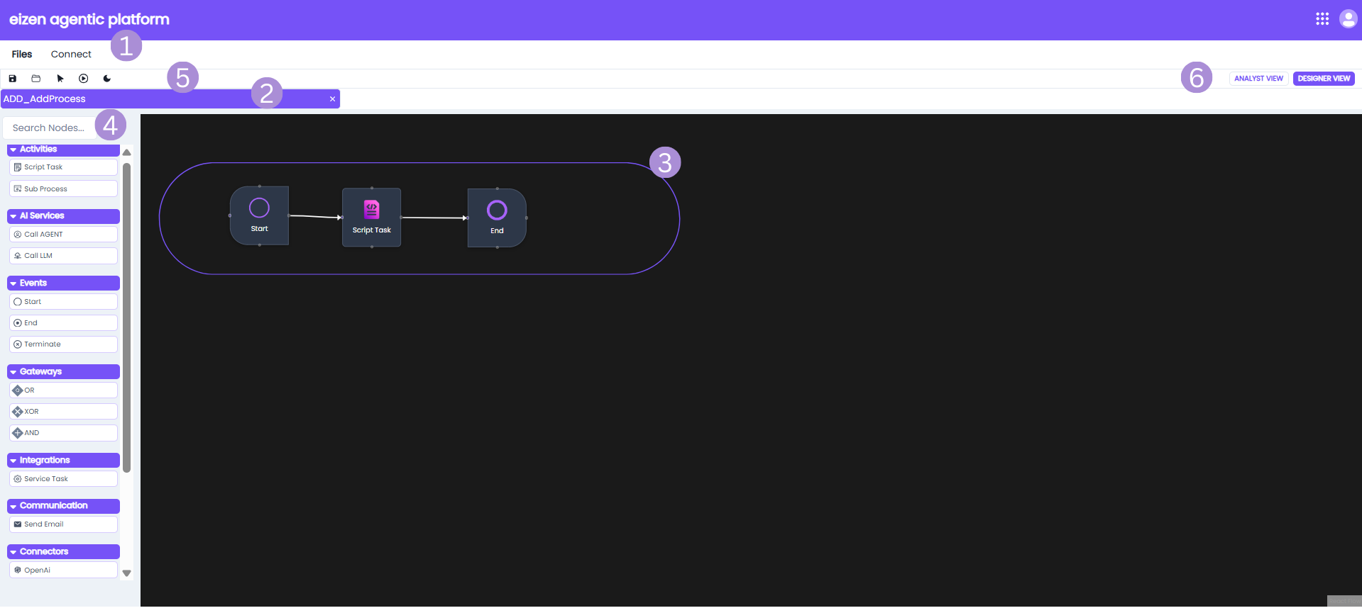
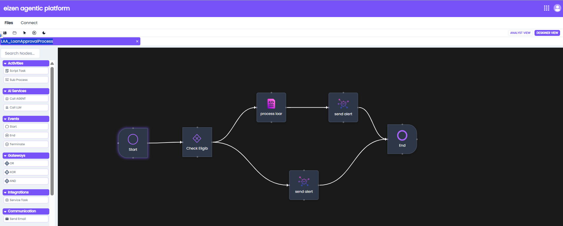
This page discusses the basic features and functionality of process models and the Process Modeler.
| Sno | Element | Description |
|---|---|---|
| 1 | Menu Bar | The menu bar has features are helpful when working with process models. |
| 2 | Process Model Status Tab | The tab shows the name of the process model and the version currently open on the canvas. |
| 3 | Process Model Canvas | The canvas is where you can drag nodes and start connecting your activities. |
| 4 | Search bar and Workflow | This search bar allows you to quickly search for any nodes. The Workflow Palette lists out all nodes you can add to the process model. The connectors, integration and communication panels lists various third-party integration options that can be used within the process model. These connectors allow the workflow to interact with external platforms and services. |
| 5 | Process Model Toolbar | The toolbar offers a set of tools that make it easy to create and manage processes while working on the canvas. |
| 6 | Process Model Role View | In a process model, you can choose between the Analyst View and the Designer View. The Analyst View is used for creating high-level workflow diagrams, while the Designer View offers more advanced configuration options and allows you to publish the process model. |
Creating a Process Model
To create a process model:
- In your application go to application view, select an application and either click on the application name or go to object view.
- Click the Create New drop down and select Process.
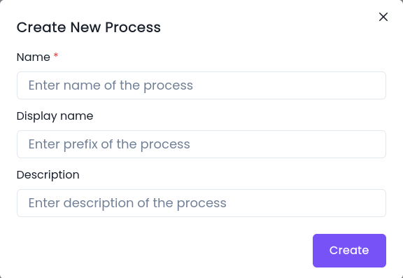
- Configure the following properties:
- Name
- Display Name
- Description
- Click create.
Analyst View
The Analyst View offers flow chart tools that include standard activities, events, and gateways. These elements, or process nodes, have minimal configuration settings, making it easy for analysts to outline the general workflow without needing to define data, assign users, or set properties like task forms.
To turn this basic flowchart into a fully functional process model that your application can run, you’ll need to switch over to the Designer View.
Designer View
This view includes all the modeling and documentation capabilities available in the Analyst View, with the added ability to double-click on activities, gateways, or events to configure business rules, define variables, and attach forms.
Menu Bar Options
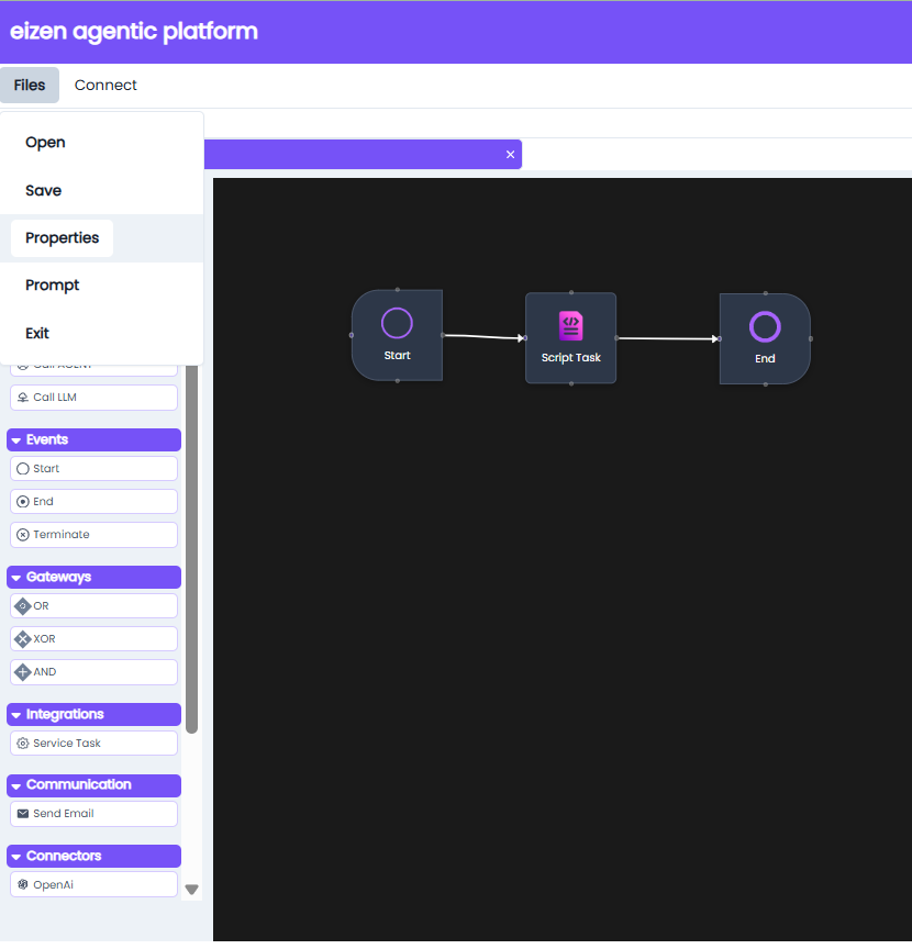
File Menu
| Option | Description |
|---|---|
| Open | Open other process models from your files. |
| Save | Saves all changes to the process model in the database. |
| Properties | Opens a dialog that provides all options for process model properties. |
| Exit | Closes process modeller. |
Connect
Allows connection between events and/or gateways.
Search Bar and Workflow
| Section | Element | Description |
|---|---|---|
| Search | Search Nodes  | Search bar to quickly find a node by name. |
| Activities | Script Task  | Executes backend logic or scripts (e.g., Groovy) within the process. |
Sub Process 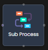 | Calls another process model for modular or reusable process logic. | |
| AI Services | Call Agent  | Invokes a predefined intelligent agent for automated decisions or actions. |
Call LLM  | Sends input to a Large Language Model (LLM) for natural language processing or tasks. | |
| Events | Start  | Marks the beginning of a process flow. |
End  | Indicates successful or expected end of a process. | |
Terminate  | Immediately stops all activities and ends the process. | |
| Gateways | OR  | Executes one or more paths based on conditions (inclusive). |
XOR  | Executes only one path based on a condition (exclusive). | |
AND  | Executes all outgoing paths simultaneously (parallel). | |
| Integrations | Service Task  | Executes system-level tasks like API calls to external systems. |
| Communication | Send Email  | Sends an email notification as part of the process flow. |
| Connectors | AGENT  | Internal or custom AI agent for specialized automation. |
LLM  | LLM connector. |
Toolbar Options
| Action | Icon | Properties |
|---|---|---|
| Save | Saves process to the database. | |
| Connect | Allows connection between events and/or gateways. | |
| Run or Trigger Pipeline | Executes or triggers a predefined pipeline. Helps you test and validate your process flow end-to-end in a controlled environment. | |
| Theme Toggle | Switch between light or dark mode. |
Process Model Canvas
The Process Model Canvas shows the visual layout of a workflow using nodes and connectors and allows you to drag and drop various elements from the nodes palette and connect them together.
Canvas Annotations
To add annotations to the canvas, click the text box beneath a node to edit its label or name.
Node Configuration
To configure a node, double click the node which opens tabs:
Example: LAA_LoanApprovalProcess (Process Model)
Important Note on Variables
- Before configuring Inputs or Outputs in any node, you must first define the necessary variables.
Variables are created in the Properties dialog (accessible from the File → Properties → Variables option in the menu bar). - Without defining variables beforehand, inputs and outputs cannot be properly stored or referenced during process execution.
Process Model Properties
The Process Model Properties dialog provides configuration options for naming, describing, and managing variables in a process model.
It can be accessed from the File → Properties option in the menu bar.
General Tab
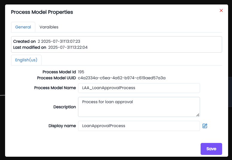
The General tab displays metadata and identification details of the process model:
- Created on: The timestamp when the process model was initially created.
- Last modified on: The timestamp of the most recent update to the process model.
- Process Model ID: A unique system-generated identifier for the process model.
- Process Model UUID: A universally unique identifier for the process model instance.
- Process Model Name: The internal name of the process model (e.g.,
LAA_LoanApprovalProcess). - Description: A user-defined description of the process model’s purpose.
- Display Name: The display-friendly name of the process model, shown in the application (e.g.,
LoanApprovalProcess).
Variables Tab
The Variables tab is used to define input and output variables that a process model can use.
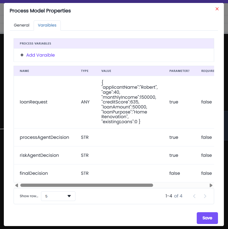
- Use the Add Variable option to create new variables.
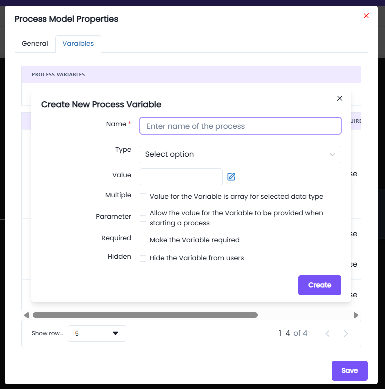
Fields in Create New Process Variable
- Name*: Enter a unique name for the process variable.
- Type: Select the data type of the variable.
- You can use basic data types like
Integer,String,Boolean, etc. - If a custom data type was created earlier (under Design Objects → Custom Data Type), it can also be selected here.
- You can use basic data types like
- Value: Provide a default value for the variable (optional).
- Multiple: Enables the variable to hold an array of values instead of a single value.
- Parameter: Marks the variable as a parameter, meaning its value can be supplied when starting the process.
- Required: Ensures the variable must have a value before process execution.
- Hidden: Hides the variable from users, useful for internal system variables.
⚠️ Important: Without defining variables here, nodes will not be able to generate or store data during execution.
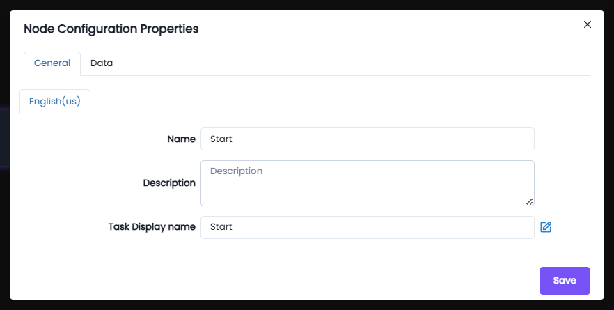
Start node:
General: The general tab has basic settings in which you can update the name, write a description and choose a task display name.
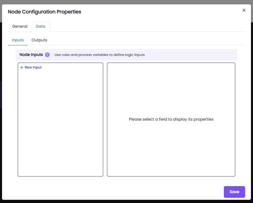
Data:
The Data tab lets you define how data flows into and out of a node in the process model. You're looking specifically at the Outputs section, where node results are saved into process variables.
- + New Input is to pass data into the node. The × Delete button can be used to to remove an expression.
- The Output is used to store results from the node into a process variable .
- The New Expression block is used to define a custom expression that calculates a value or retrieves data during process execution.
- The Expression editor field is where you write logic which will be evaluated during runtime.
- The Target drop down allows you to select the process variable that will receive the result of your expression. You can choose any defined variable in the process
- The Save button confirms and applies the output mapping to the node.
XOR node: (Check Eligibility)
- We can change the name of the node.
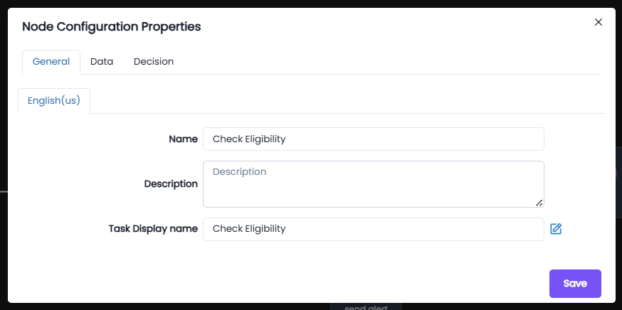
Decision: The Decision tab only appears for the logic gates, this tab configures the routing logic for the chosen gateway. For example this is the decision tab for the XOR gateway:
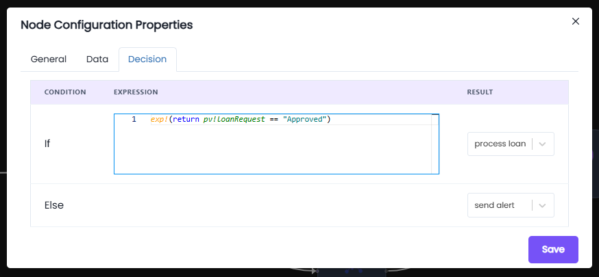
Understanding pv:
- The prefix
pvstands for Process Variable. - Process Variables are the data elements created and managed in the workflow.
- These variables are defined under the Properties → Variables option in the File menu of the process modeler.
- Using
pv!variableNameallows tasks, gateways, and service integrations to access or update the value of that variable during execution.
Behavior:
- If the condition in the
ifstatement is satisfied →
The process flow moves to the process loan (Script Task). - If the condition is not satisfied (
else) →
The process flow is directed to the send alert (Service Task).
Script Task node: (process loan)
The Outputs tab in Node Configuration Properties allows you to define how data generated inside a node is saved into process variables for use elsewhere in the process model.
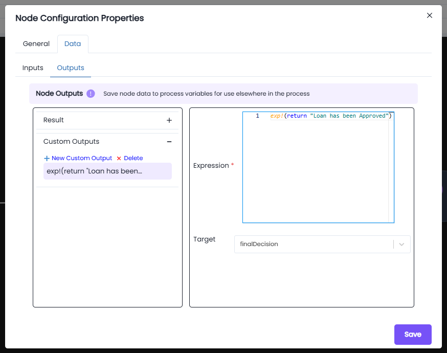
Fields in Outputs:
-
Result: Default output variable where the result of the node is stored.
-
Custom Outputs: Allows you to define additional outputs for the node.
- Click + New Custom Output to add one.
- Custom outputs are useful when multiple values need to be returned from the same node.
-
Expression*:
- Defines the logic or script that generates the output.
- For example:
This expression evaluates and returns
exp!{ return "Loan has been Approved" }"Loan has been Approved"as the output.
-
Target:
- The process variable where the result of the expression will be stored.
- Example:
finalDecision
Service Task node: (send alert)
The Service Task allows integration of external services or automated logic into the process.
In this configuration, Node Inputs are defined using expressions that determine what data should be passed into the service.
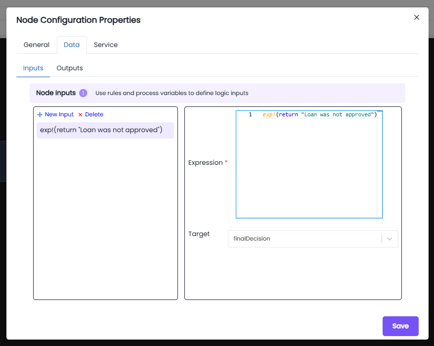
Inputs:
- Expression:
exp!({ return "Loan was not approved"; })
This expression sets the value of the input parameter.
- Target Variable:
The output of the expression is stored in the process variable
finalDecision, which can then be used elsewhere in the process flow.
Behavior:
- When the Service Task executes, the output expression is run.
- The result is captured and stored in the defined target variable.
- This Service Task is executed only when the XOR Gateway takes the else path.
- Gateways (e.g., XOR Gateway) can then use this stored variable to determine the next path of the process.
Notes:
- Inputs can be configured as constants, expressions, or references to process variables.
- Ensure that the Target variable is already created under Process Variables in the Process Model Properties.
- Inputs play a key role in decision-making and routing within the process.
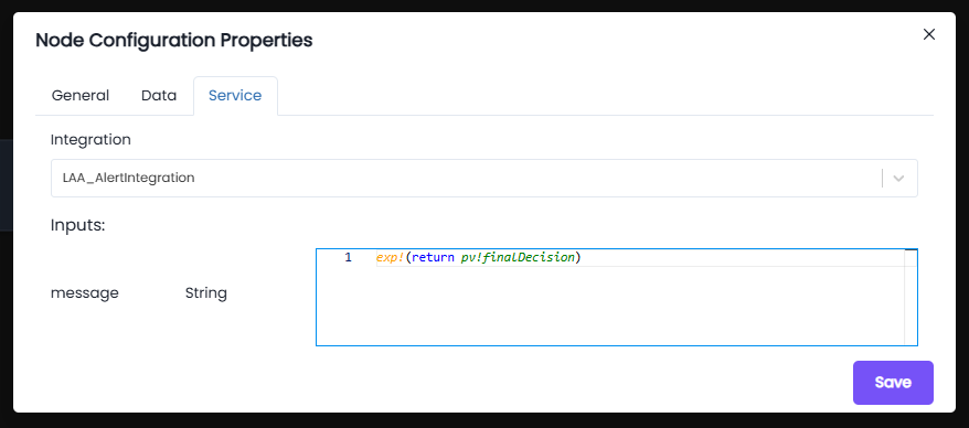
Service Task – service pane
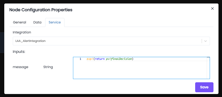
Integration:
- Integration Used:
LAA_AlertIntegration - This integration handles external alert/notification services.
Inputs:
- message (String):
exp!( return pv!finalDecision) - The input expression retrieves the value of the process variable finalDecision.
- This ensures the exact decision message (e.g., "Loan was not approved") is passed to the alert service.
Behavior:
- The Service Task sends an alert with the message derived from finalDecision.
- This task only executes when the XOR Gateway condition evaluates to false (loan not approved).
- The alert ensures stakeholders/applicants are notified immediately when their loan application is rejected.
Notes:
- Ensure that pv!finalDecision is properly updated in previous tasks (e.g., Script Task or Data Mapping).
- The integration LAA_AlertIntegration must be correctly configured in the system to handle notifications.
- Input data type is String – custom messages should always resolve to a string value.
- This Service Task acts as the final communication step in the rejection flow of the process.
Service Task node-2: (send alert)
This Service Task is responsible for sending an approval notification when the loan is approved.
It is executed when the XOR Gateway follows the if path, i.e., the loan approval condition is satisfied.
Integration:
- Integration Used:
LAA_AlertIntegration - This integration is responsible for sending out approval alerts/notifications.
Inputs:
-
message (String):
exp!( return pv!finalDecision) -
The input expression fetches the value stored in the process variable finalDecision.
-
This ensures the approval message (e.g., "Loan has been Approved") is passed to the alert service.
Behavior:
- Once the Script Task evaluates the loan and sets the process variable finalDecision, this Service Task uses that result as input to send the approval notification.
- The Service Task ensures that applicants/stakeholders are informed immediately when their loan request is approved.
- This path is triggered only when the XOR Gateway condition evaluates to true.
Notes:
- The finalDecision process variable must already be created and updated by the preceding Script Task.
- Integration LAA_AlertIntegration must be properly configured to send approval alerts.
- Input type is strictly String; ensure the Script Task always resolves to a valid string.
- This Service Task complements the rejection alert task, covering the positive flow of the process.
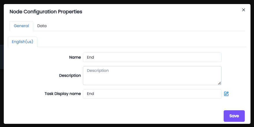
End node:
General: The general tab has basic settings in which you can update the name, write a description and choose a task display name.
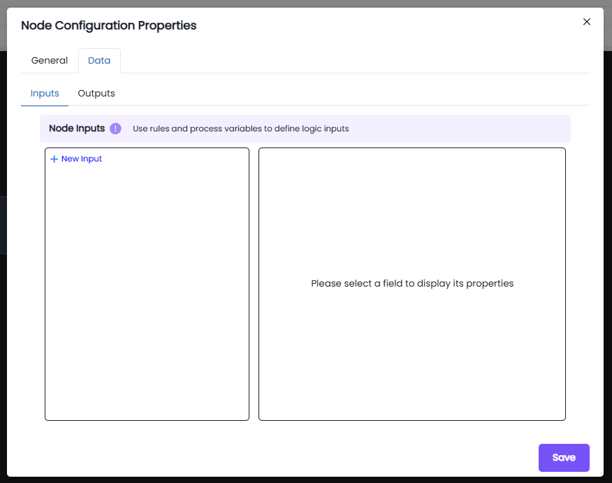
Data:
The Data tab lets you define how data flows into and out of a node in the process model. You're looking specifically at the Outputs section, where node results are saved into process variables.
- + New Input is to pass data into the node. The × Delete button can be used to to remove an expression.
- The Output is used to store results from the node into a process variable .
- The New Expression block is used to define a custom expression that calculates a value or retrieves data during process execution.
- The Expression editor field is where you write logic which will be evaluated during runtime.
- The Target drop down allows you to select the process variable that will receive the result of your expression. You can choose any defined variable in the process
- The Save button confirms and applies the output mapping to the node.
Node Functionality:
- Each node works based on its functionality and interacts with process variables (
pv!), input variables (iv!), or process models (pm!) depending on its role. - This ensures the workflow executes seamlessly and logically from start to end.